
 Search
Convert Gauge Cluster Bulbs to LED's. 02-03 - By knight_yyz
Page 1 of 1
![]()
 Convert Gauge Cluster Bulbs to LED's. 02-03 - By knight_yyz
![]() by Ghost Mon Mar 16, 2009 8:28 pm
by Ghost Mon Mar 16, 2009 8:28 pm
This "How To Do" was written by a fellow member here on TMEC Toronto Maxima site (knight_yyz) and is very well written complete with pictures and links for your supplies. I had saved this How To Do prior to the site being hacked and lost like so many other well written articles
Please direct all question to knight_yyz and requests for assistance, I believe also is willing to do this mod for you, so PM him for pricing.
What you will need:
Soldering iron and solder, electrical tape or shrink wrap. A few feet of 18 or 20 gauge wire, preferably 3 colors to differentiate between +ve and -ve.
4 led's for the cluster lights, 2 more if you want to do the signals.
NOTE: The 02-03 gauge cluster has a blue film on it. Most people think the cluster looks green. That is because the OEM filament bulbs give off a yellow hue. Yellow bulb and blue film will give you green. If you want blue, use white LED's. If you want red get the brightest red possible. I know red works, but don't forget that red + blue = purple.
I suggest you get these (LED's) http://cgi.ebay.com/10PC-0-5W-StrawHat-8mm-140-HighPower-White-LED-110Kmcd_W0QQitemZ310044715268QQihZ021QQcategoryZ66954QQtcZphotoQQcmdZViewItemQQ_trksidZp1742.m153.l1262
Note, before you solder anything you must use a process called tinning. Always dip the end of the wire in the flux, add heat then a bit of solder. Same with the pins, add a drop of flux, then heat then a drop of solder. It makes life much easier.
Ok, step one is to remove the cluster from the car. Bring it into the house and place it on a nice work area.
We need to do some calculations... We all know that to run an LED on a 14V system we will need to add the appropriate resistor. In order to do that we need some information about the LED. The link I posted has everything you need.
We need to know the DC forward Voltage and the DC forward Current.
In this case DC Forward voltage is 3.0V and the forward current is 100ma.
If we go online to (This Web Site) http://led.linear1.org/led.wiz you punch in the numbers.
Source voltage is 14V (14.4 is more accurate)
DC V is 3
DC current is 100
4 leds in the array...
and voila, we need a 20 Ohm resistor rated at 1/2 watt. This can be bought at a local electronic shop.
Ok so we have a complicated circuit now. To make the circuit a little easier i suggest making 2 circuits with 2 leds. This will change the resistor size, and we will need two instead. So with the new array being only 2 LED's we get the following information.
80 ohms at 1 watt. So buy two of those.
Now we can figure out where we need to solder. Some people prefer to tap right into the harness. I will tell you right now it is a PITA to do that. Trying to splice into a wire in a harness is not easy. Fortunately the Nissan gauge has small metal pins which we can solder to directly.
We are going to use the following pins.
#64 is the +ve for the cluster bulbs, and #20 is the -ve or ground.

Tin this pin. (#64) That is place a small drop of flux on the pin, then heat it with the soldering iron and add a small amount of solder. Then tin the end of a piece of red wire and solder it to the pin.

Do the same to this pin, but use a black wire

On an LED there is a short leg and a long leg. The shorter leg is negative and the long leg is positive. I usually solder the resistor directly to the LED. Use shrink wrap to protect the legs after you solder your wires. You will be making two circuits. Choose how you want to do it. Make the two left bulbs one circuit, or the two top. Whatever floats your boat. The resistor can go on the negative or the positive lead. Doesn't matter as long as it is in the circuit.
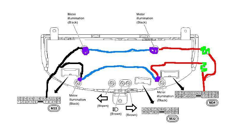
Now you just have to make the circuit. Power source is pin 64. so to the end of that red wire we solder the resistor. Tin both ends; you can cut the legs a little shorter if you like. Then solder to the longer end of the 1st led. Make sure it can reach the socket it will be sitting in. You may need to add a piece of wire to do this. On the short end of that led you solder a piece of blue/yellow/green wire. This must be long enough to be soldered to the positive side of the second led in the array. Then solder a black wire to the short end of led #2 and solder the other end to the black wire at number 20.
Red line is red wire, blue line is 'common wire' purple is the led, and green squiggle is the resistor
To do the signals repeat the procedure but use these pins.
#25 is positive for LH signal, #29 is positive for RH signal. Ground is #30 on M32 plug

But, for the signals, 2 circuits, only one LED on each with a common ground. So recalculate the resistors needed as they are separate power supply.

Make sure you dont get them backwards, or the right will flash when you go left and vice versa.
If you want to get really fancy you can find the led holders and use them as well. But they will block the dispersion of the leds as they will sit too low. Notice the leds I picked have 140* of dispersion to reduce hot spots. Holders are usually only good for about 100*

Posted here for safe keeping and will repost for Ray on TMEC when it finally stabilizes
What you will need:
Soldering iron and solder, electrical tape or shrink wrap. A few feet of 18 or 20 gauge wire, preferably 3 colors to differentiate between +ve and -ve.
4 led's for the cluster lights, 2 more if you want to do the signals.
NOTE: The 02-03 gauge cluster has a blue film on it. Most people think the cluster looks green. That is because the OEM filament bulbs give off a yellow hue. Yellow bulb and blue film will give you green. If you want blue, use white LED's. If you want red get the brightest red possible. I know red works, but don't forget that red + blue = purple.
I suggest you get these (LED's) http://cgi.ebay.com/10PC-0-5W-StrawHat-8mm-140-HighPower-White-LED-110Kmcd_W0QQitemZ310044715268QQihZ021QQcategoryZ66954QQtcZphotoQQcmdZViewItemQQ_trksidZp1742.m153.l1262
Note, before you solder anything you must use a process called tinning. Always dip the end of the wire in the flux, add heat then a bit of solder. Same with the pins, add a drop of flux, then heat then a drop of solder. It makes life much easier.
Ok, step one is to remove the cluster from the car. Bring it into the house and place it on a nice work area.
We need to do some calculations... We all know that to run an LED on a 14V system we will need to add the appropriate resistor. In order to do that we need some information about the LED. The link I posted has everything you need.
We need to know the DC forward Voltage and the DC forward Current.
In this case DC Forward voltage is 3.0V and the forward current is 100ma.
If we go online to (This Web Site) http://led.linear1.org/led.wiz you punch in the numbers.
Source voltage is 14V (14.4 is more accurate)
DC V is 3
DC current is 100
4 leds in the array...
and voila, we need a 20 Ohm resistor rated at 1/2 watt. This can be bought at a local electronic shop.
Ok so we have a complicated circuit now. To make the circuit a little easier i suggest making 2 circuits with 2 leds. This will change the resistor size, and we will need two instead. So with the new array being only 2 LED's we get the following information.
80 ohms at 1 watt. So buy two of those.
Now we can figure out where we need to solder. Some people prefer to tap right into the harness. I will tell you right now it is a PITA to do that. Trying to splice into a wire in a harness is not easy. Fortunately the Nissan gauge has small metal pins which we can solder to directly.
We are going to use the following pins.
#64 is the +ve for the cluster bulbs, and #20 is the -ve or ground.
Tin this pin. (#64) That is place a small drop of flux on the pin, then heat it with the soldering iron and add a small amount of solder. Then tin the end of a piece of red wire and solder it to the pin.
Do the same to this pin, but use a black wire
On an LED there is a short leg and a long leg. The shorter leg is negative and the long leg is positive. I usually solder the resistor directly to the LED. Use shrink wrap to protect the legs after you solder your wires. You will be making two circuits. Choose how you want to do it. Make the two left bulbs one circuit, or the two top. Whatever floats your boat. The resistor can go on the negative or the positive lead. Doesn't matter as long as it is in the circuit.
Now you just have to make the circuit. Power source is pin 64. so to the end of that red wire we solder the resistor. Tin both ends; you can cut the legs a little shorter if you like. Then solder to the longer end of the 1st led. Make sure it can reach the socket it will be sitting in. You may need to add a piece of wire to do this. On the short end of that led you solder a piece of blue/yellow/green wire. This must be long enough to be soldered to the positive side of the second led in the array. Then solder a black wire to the short end of led #2 and solder the other end to the black wire at number 20.
Red line is red wire, blue line is 'common wire' purple is the led, and green squiggle is the resistor
To do the signals repeat the procedure but use these pins.
#25 is positive for LH signal, #29 is positive for RH signal. Ground is #30 on M32 plug
But, for the signals, 2 circuits, only one LED on each with a common ground. So recalculate the resistors needed as they are separate power supply.
Make sure you dont get them backwards, or the right will flash when you go left and vice versa.
If you want to get really fancy you can find the led holders and use them as well. But they will block the dispersion of the leds as they will sit too low. Notice the leds I picked have 140* of dispersion to reduce hot spots. Holders are usually only good for about 100*
Posted here for safe keeping and will repost for Ray on TMEC when it finally stabilizes

Ghost- Number of posts : 207
Location : Burlington, Ontario
Registration date : 2008-04-21
![]()
![]()
![]()


Page 1 of 1
Permissions in this forum:
You cannot reply to topics in this forum